- E-mail: admin@yaweitransformer.cn
- Tel: +86-18862719076
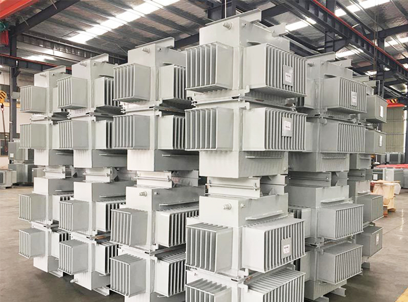
1. In order to solve the heat dissipation problem of the main transformer in the whole household substation, the mechanical structure of the transformer is first solved. The split type transformer is adopted, and the transformer body and the radiator are separated to increase the thermal radiation area of the transformer.
2, the transformer low, transformer placed in the room at a lower temperature area, enhance the transformer heat dissipation effect.
3, the use of low loss transformer, reduce winding temperature rise.
4. Reasonable selection of ventilation window area. Each split transformer is equipped with 16 groups of radiators, which are separately arranged in a room. Two 2.5m×1.5m ventilation shutters are set at the lower part of each radiator room, and the upper part of the radiator room is not capped, so as to not affect the operator’s inspection of the radiator, but also to ensure that the radiator room has enough air intake area and adopts natural ventilation. The transformer body room is equipped with ventilation louver inlet, with an area of about 15m2 and a height of 1.5m, which is easy for operators to inspect. The roof is equipped with two 1.5m×1.5m×8.4m ventilation shafts, which adopt the form of upper and lower direct air, and make use of the chimney effect principle and optimized ventilation structure to make it have a strong heat dissipation capacity.
5, in addition to the air inlet window and ventilation shaft, another mechanical exhaust – low noise axial flow fan, jointly complete the transformer body room ventilation task, so that the summer transformer load is full, the exhaust fan into operation.
The way of heat dissipation of the transformer should not harm the various parts of the transformer, and there is no potential threat to the operator of the transformer, so the heat dissipation of the transformer is more critical, and the first is to be safe!
