- E-mail: admin@yaweitransformer.cn
- Tel: +86-18862719076
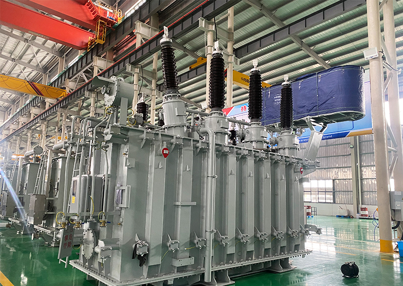
How to detect and configure the power transformer? In order to better solve the problems of the majority of users, today’s Founder transformer is talking about the detection and configuration skills of power transformers.
The function of power transformer is power transmission, voltage conversion and insulation isolation, as a major soft magnetic component, in power technology and power electronics technology has been widely used. According to the size of the transmission power, the power transformer can be divided into several grades: more than 10kVA for high power, 10kVA ~ 0.5kVA for medium power, 0.5kVA ~ 25VA for small power, and below 25VA for micro power. Transmission power is different, the design of the power transformer is not the same, should be self-evident.
A. Check whether there are obvious anomalies by observing the appearance of the transformer: such as whether the coil lead is broken, de-soldering, whether the insulation material has burnt marks, whether the core fastening screw is loose, whether the silicon steel sheet is rusted, whether the winding coil is exposed, etc.
B, insulation test: with a multimeter R×10k stop respectively measure the core and primary, primary and secondary, core and secondary, electrostatic shielding layer and secondary, secondary winding resistance value, the multimeter pointer should refer to the infinite position. Otherwise, it indicates that the insulation performance of the transformer is poor.
C, coil on-off detection: the multimeter is placed in R×1 stop, test, if the resistance value of a winding is infinite, it indicates that this winding has open fault.
D, the primary identification, secondary coil: the primary and secondary pins of the power transformer are generally drawn from both sides, and the primary winding is marked with 220V words, the secondary winding is marked with rated voltage, such as 15V, 24V, 35V and so on. And then identify them based on these markers.
E, no-load current detection:
(a) Direct measurement method: all secondary windings are open, the multimeter is placed in AC current stop 500mA, and the primary winding is connected in series. When the plug of the primary winding is inserted into the 220V AC mains, the no-load current value is indicated by the multimeter. This value should not be greater than 10% to 20% of the transformer full load current. Generally, the normal no-load current of the power transformer for electronic equipment should be about 100mA. If it exceeds too much, it indicates that the transformer has a short-circuit fault.
(b) Indirect measurement method: a resistance of 10/5W is connected in series in the primary winding of the transformer, and the secondary is still all empty. Set the multimeter to AC gear. After powering up, use two pens to measure the voltage drop U at both ends of the resistance R, and then use Ohm’s law to calculate the no-load current I null, that is, I null =U/R.
F, no-load voltage detection: the primary power transformer is connected to 220V mains, and the AC voltage of the multimeter is connected in turn to measure the no-load voltage value of each winding (U21, U22, U23, U24) should meet the required value, and the allowable error range is generally: The high voltage winding is ≤± 10%, the low voltage winding is ≤± 5%, and the voltage difference between the two groups of symmetric windings with center tap should be ≤± 2%.
G, the general low-power power transformer allows the temperature rise of 40 ° C ~ 50 ° C, if the quality of the insulation material used is better, the allowable temperature rise can be increased.
H, detect and distinguish the same end of each winding: When using a power transformer, sometimes in order to get the required secondary voltage, two or more secondary windings can be used in series. When the power transformer is used in series, the same end of each winding participating in series must be correctly connected and cannot be mistaken. Otherwise, the transformer will not work properly.
